Constraint: PTSF
Model ElementConstraint_PTSF defines a higher pair constraint. A fixed point on one body slides on a surface that is fixed on a second body. The point is not allowed to lift off the surface.
Format
<Constraint_PTSF
     id             =     "integer"
     label          =     "Name of Constraint_PTSF element"
     i_marker_id    =     "integer"
     j_marker_id    =     "integer"
 [
     disp_xo        =     "real"
     disp_yo        =     "real"
     disp_zo        =     "real"
 ]
     surface_id     =     "integer"  >
/>
Attributes
- id
- Element identification number (integer>0). This number is unique among all Constraint_PTSF elements.
- label
- The name of the Constraint_PTSF element.
- i_marker_id
- Specifies a Reference_Marker that defines the connection on the first body. The origin of this Reference_Marker defines the point that is required to slide on the surface. The body containing this Reference_Marker may be a rigid body, a flexible body, or a point body. The parameter is mandatory.
- j_marker_id
- Specifies a Reference_Marker that defines the the coordinate system in which the surface points are defined. The surface is defined on the body containing this Reference_Marker and moves with this body. The body containing the curve must be a rigid body or a point body. The parameter is mandatory.
- disp_x0, disp_y0, disp_z0
- Defines a guess for the initial contact point on the surface. The coordinates are measured with respect to j_marker_id and are defined in its coordinate system. The parameter is optional. 2
Example
The image below shows a spatial cam-type sine generator.
Slide cam 1 rotates about a fixed axis y-y and has a plane working surface 'a' whose normal makes an angle β with the axis y-y. Follower 2 slides in a fixed guide S whose axis x-x is parallel to the axis y-y. Follower 2 carries a ball B of small radius in a holder (not shown) fixed to the follower.
When cam 1 is turned by an angle α, the point of contact of ball B with the surface 'a' is displaced by the distance.
z = R . tan (β) . sin (α)
R is the distance between the axes y-y and x-z. Thus, the displacement of follower 2 is proportional to the sine of the angle α, the angle of rotation of the cam.
- Reference_Marker 1101 is placed at the center of surface 'a', with its z-axis along the normal to the surface. Its x-axis is aligned such that at the initial configuration, the contact point between the ball and the surface, lies on this axis. Assume that the distance between the axes y-y and x-x is 100mm.
- Surface 'a' is denoted by Reference_Surface 11 in the MotionSolve model. This surface is defined with respect to Reference_Marker 1101.
- Reference_Marker 2101 is placed at the center of ball B, which is assumed to be the contact point between the ball and the surface.
- Constraint_PTSF 1 defines the contact between the ball B and the surface 'a'.
 Figure 1. A Spatial Cam Sine Generator
The Constraint_PTSF object for the above system is:
<Constraint_PTSF
     id            = "1"
     Label         = "Advanced Joint Name"
     i_marker_id   = "2101"
     j_marker_id   = "1101"
     disp_xo       = "100.0"
     disp_yo       = "0.0"
     disp_zo       = "0.0"
     surface_id    = "11"
/>
Comments
- Constraint_PTSF defines a higher pair
constraint, where a fixed point on one body (Body 1) is required to slide along a
surface defined on a second body (Body 2). This is shown schematically in the image
below. Constraint_PTSF removes only one degree of freedom.
The surface is represented parametrically using a Constraint_ParamSurface object. The surface points are defined with respect to the origin of Reference_Marker J. The coordinates are measured in the coordinate system associated with Reference_Marker J. The surface is required to be fixed with respect to Body 2.
The origin of Reference_Marker I defines a fixed point on Body 1. Body 1 may be any kind of body - Body_Rigid, Body_Flexible or Body_Point.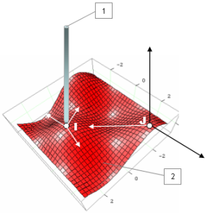 Figure 2. An illustration of a Point-on-Curve Constraint
 - The attributes disp_x0,
disp_y0, and disp_z0 define the initial
contact point on the surface. This point, denoted as P0 in the image
below, need not exactly be on the curve.MotionSolve finds the nearest point on the curve P to P0. The initial point on the curve is used to calculate an initial value of the surface parameters u0 and v0. An iterative process is used.
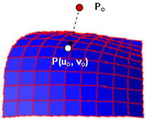 Figure 3. Calculation of the initial contact point P(u0,
v0)
Figure 3. Calculation of the initial contact point P(u0,
v0) - This constraint does not ensure that the contact point stays in the range of data specified for the surface. Additional forces at the end need to be defined to meet this requirement. Similarly, the surface is assumed to have no holes. These have to be modeled explicitly using FORCE elements available in MotionSolve.
- Both open and closed surfaces are supported. A surface may be closed on one or both of the parameters.
- The surfaces are required to be smooth to second order, or in other words, to have uniquely defined first and second derivatives with respect to the curve parameter everywhere. A non-smooth surface causes numerical difficulties.
- The function PTSF(...) may be used to extract a component of the reaction force at the contact point in any direction.
- Constraint_PTSF does not permit lift-off. You can look at the reaction force to determine if there is a tendency for the point follower to lift-off the curve. If the component of the reaction force along the normal at the contact point is positive, the "contact" force is repulsive. If the value is negative, the "contact" force is attractive, and therefore the point-follower would have separated from the curve if the constraint were not there.
- If you notice an "attractive" reaction force, you might consider modeling the subsystem using the Force_Contact object that allows lift-off to occur.