Hollow Circular Beam under a Twist Load
Model Description
Model location: <altair>\utility\mbd\nlfe\validationmanual\model1.mdl
This model consists of a straight cantilever beam of a hollow circular cross-section. The beam is subjected to a torsion load at its endpoint as shown in Figure 1 below.

Figure 1. A Beam of Hollow Circular Cross Section Fixed at One End and Subject to Torsion at the Other
- Twist angle
- Shear strain
- Beam length
- Beam radius.
- Polar moment of inertia about the beam axis.
- Shear modulus
- Young's modulus
- Poisson ratio
Multibody Model
The cantilever beam is modeled using 10 NLFE beam elements in MotionSolve. NLFE beam elements with a hollow tube section are used by specifying an inner and outer radius. The cantilever beam is fixed to the ground by a fixed joint. Gravity is turned off for this model.
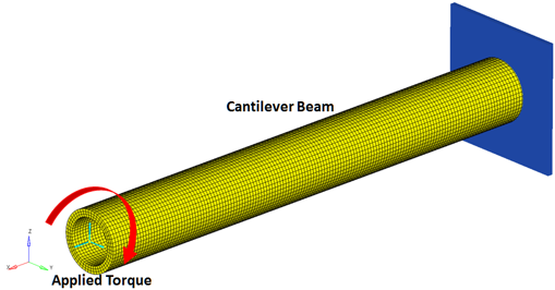
Figure 2. The Cantilever Beam Modeled in MotionView
θ = 0.026686rad
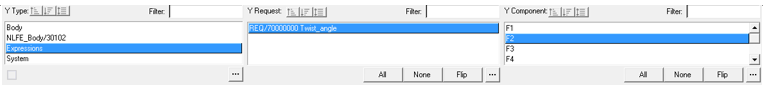
Figure 3. Plotting the Twist Angle Output
Numerical Results
The multibody model described in the previous section is run for an end time of 5.0 seconds. The output request is plotted below.

Figure 4. Twist Angle of the Marker on NLFE Associated with Torque
Conclusion
The NLFE model with 10 NLFE beam elements shows close agreement to the theoretical results for this case.
| Beam Theory | Numerical | % error | |
|---|---|---|---|
| Twist Angle | 0.026686 rad | 0.026690 rad | 0.02 % |