Edge Mesh Boundary Layer Example
The boundary layer flag turned on in the Edge Mesh Attributes enables the growing of boundary layer elements on the surface outward from the edge. It is important to note that the boundary layer is not in the volume, but on the surface.
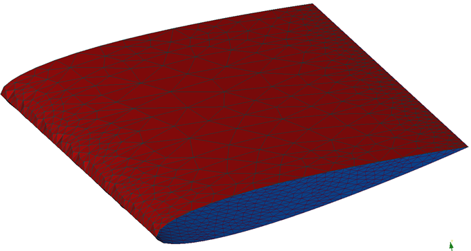
Figure 1.
The leading edge is grouped in an edge group named LeadingEdge upon importing of the geometry into AcuConsole. The mesh attributes are turned on by selecting the check mark in the box next to Edge Mesh Attributes.
The mesh size type is set to none as the refinement in the span direction is not the goal. The goal is to capture the curvature of the mesh wrapping around the leading edge on the surface.
Match Outer Layer
The boundary layer is activated by selecting On. The boundary layer type of Match outer layer was selected as to have the mesh grow to the surface mesh size using a growth rate of 1.3 and a first element height of 0.001.
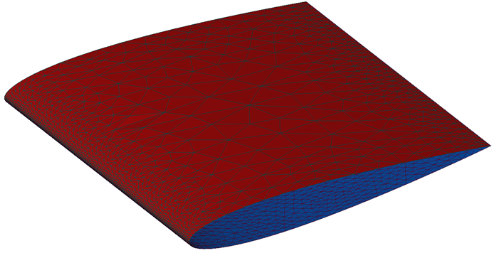
Figure 2.
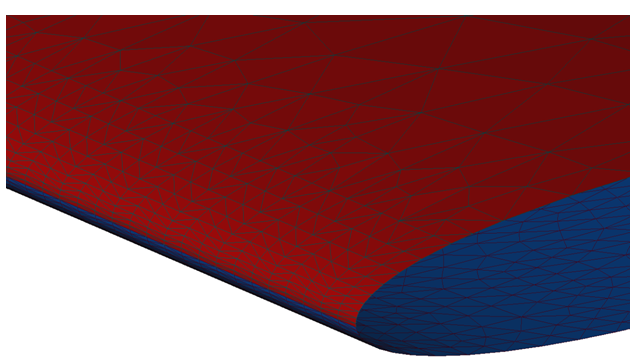
Figure 3.
Full Control
Specifying full control of the boundary layer growth allows for better control of the manner in which the boundary layer grows. Below is the same example, but using Full Control of the boundary layer instead of Match Outer Layer.
The image below shows the mesh specifications used for the full control example. The first layer height remained the same as in the Match Outer Layer example, but the total layer height as well as the number of layers was specified, establishing a growth rate of approximately 1.01.
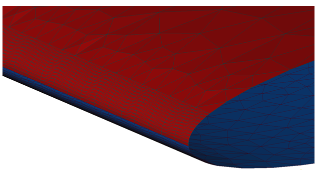
Figure 4.
Boundary Layer Elements Type
The elements used in the edge boundary layer can be mixed instead of tetrahedral. The example below shows the results of only changing the element type from triangles in the example above to mixed.
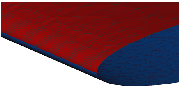
Figure 5.