HM-1030: Organize a Model
A large portion of HyperMesh functionality is organized into panels. Many panels have common attributes and controls, so once you become familiar with the features of one panel, it is much easier to understand other panels.
- Create geometry and organize it into components
- Organize elements into the components
- Rename components
- Identify and delete empty components
- Delete all of the geometry lines
- Reorder the components in a specific order
- Renumber all of the components, starting with ID 1 and incrementing by 1
- Create an assembly
- Organize the constraint
- bumper.hm
Copy the file from this directory to your working directory.
It is recommended that you review the general overview before completing this tutorial.
Retrieve the Model File
In this step you will open the model file.
-
In the Open Model dialog, navigate to your working
directory and open the bumper.hm model file.
A model appears in the graphics area.
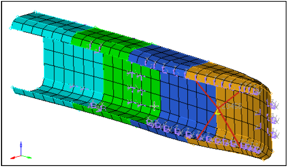
Figure 1.
Create a Component
In this step you will create a component named geometry to hold the model's geometry.
Create Geometry Lines
In this step you will create two geometry lines and organize them into different components.
-
In the graphics area, select two opposite and diagonal nodes of the same
element as illustrated in the image below:
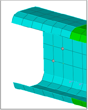
Figure 2. -
Click create.
HyperMesh creates a red line. This line is the same color as the rigid component because it is organized into the current component, rigid.
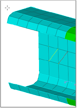
Figure 3.
Move the Model Geometry
In this step you will move the model's geometry surfaces into the component, geometry.
-
Click
 on the entity selector and select
surfs from the list of entities that can be
collected.
The entity selector is now set to surfs.
on the entity selector and select
surfs from the list of entities that can be
collected.
The entity selector is now set to surfs.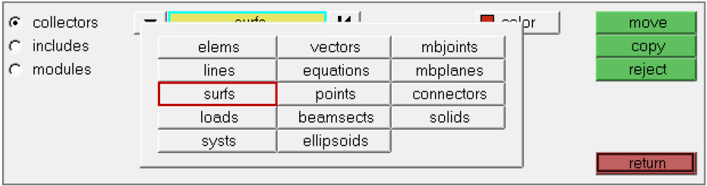
Figure 4. -
From the list of components, select geometry.
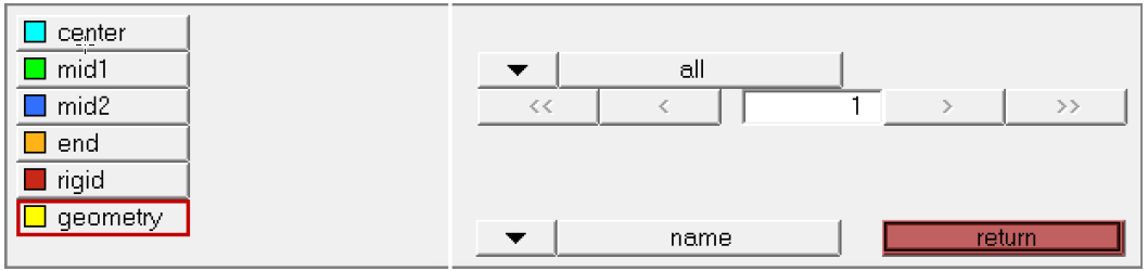
Figure 5. -
Click move.
HyperMesh moves the selected surfaces into the geometry component and colors the geometric entities yellow to match the component color.
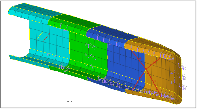
Figure 6.
Move the Model Shell Elements
In this step you will move all of the model's shell elements (quads and trias) into the component, center.
In this step, you should still be in the Organize panel, collectors subpanel.
-
Click on the entity selector, and select
elems from the list of entities that can be
collected.
The entity selector is now set to elems.
-
Select the components: mid1,
mid2, and end.
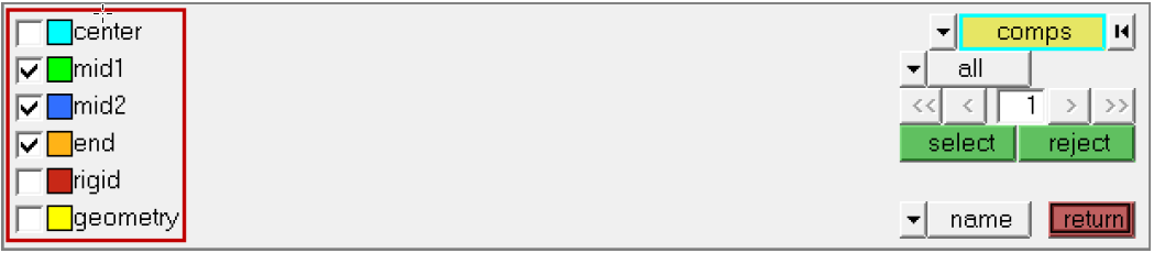
Figure 7. -
Click move.
HyperMesh moves the elements in the selected components into the center component, and colors all of the shell elements cyan blue to match the component color.
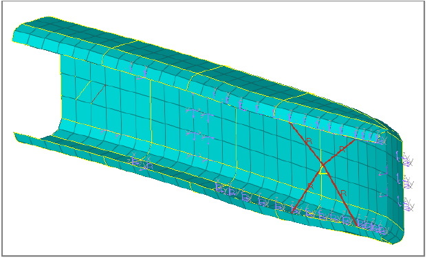
Figure 8.
Rename the Component Center
In this step you will rename the component, center, to shells.
- In the Model Browser, Component folder, right-click on center and select Rename from the context menu.
- In the editable field, rename the component to shells and then press Enter.
Identify Empty Components
In this step you will identify and delete all of the empty components.
-
Click comps.
HyperMesh displays a complete list of the model's components. The empty components are indicated with a selected check box.

Figure 9.
Delete Geometry Lines
In this step you will delete all geometry lines in the model.
For this step you should still be in the Delete panel.
Move the Component
In this step you will move the component, geometry, to the front in the components list.
-
On the right side of the panel, click the bottom switch and select
name(id).
HyperMesh displays the IDs for each component next to its name. The ID for shells is 1, the ID for rigid is 5, and the ID for geometry is 6.
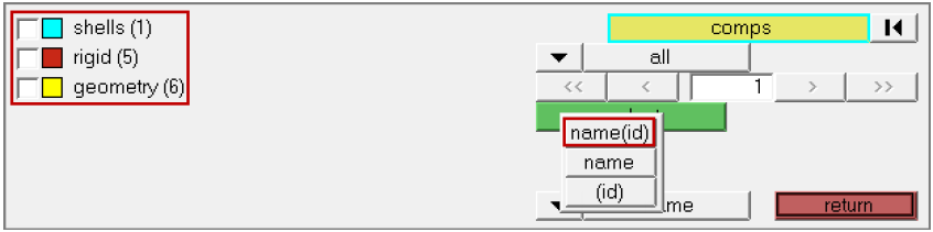
Figure 10. -
To review the reordered list of components, click comps.
The component, geometry, is at the top of the list. However, it still has the
same ID, (6).
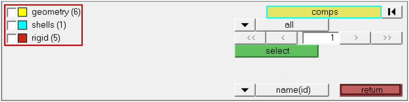
Figure 11.
Renumber Components
In this step you will renumber the components to be the same as their position in the list.
-
To review the renumbered list of components, click
comps. The components are numbered according to their
position in the list. Set the view to name(id) to see the
numbers.
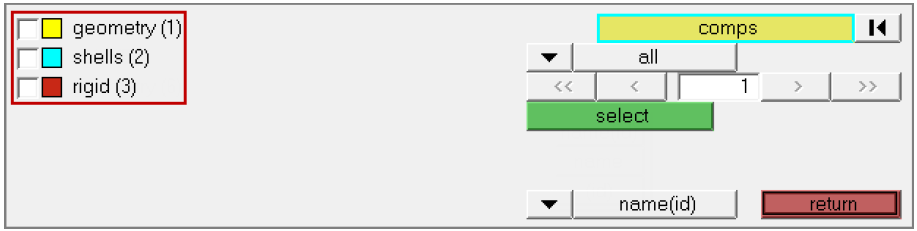
Figure 12.
Create an Assembly
In this step you will create an assembly containing the components, shells and rigid.
-
Select a Color for the assembly.
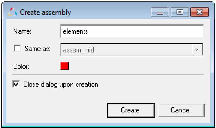
Figure 13. -
To add the selected components to the elements assembly, drag the components
using the left mouse button over the elements assembly until it highlights.
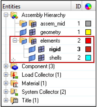
Figure 14.
Create a Load Collector
In this step you will create a load collector named constraints.
-
Click Create.
HyperMesh creates the load collector, and the Status bar displays a message that says, "Load collector created".Note: The constraints load collector is displayed in bold in the Model Browser, which indicates that it is the active load collector. Any loads that are created will be organized into this load collector.
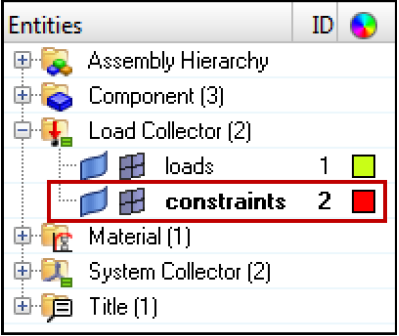
Figure 15.
Move the Model Constraint
In this step you will move the model's constraint into the load collector, constraints.
The existing load collector, loads, contains several forces and one constraint. Use the Organize panel to move the constraint into the load collector.
-
In the center of the panel, toggle from displayed to
all.
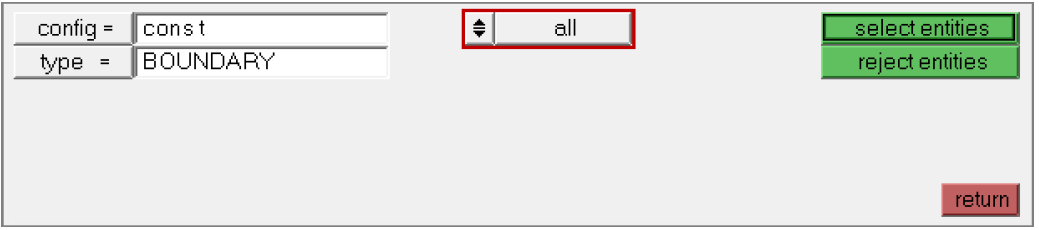
Figure 16.
Create a Component from the Model Browser
In this step you will create a component from the Model Browser.
Review Existing Assembly Elements
In this step you will review the existing assembly elements from the Model Browser.
Add Components Using the Model Browser
In this step you will add the components, geometry and component1, to the assembly, assem_mid, using the Model Browser.
Rename Assemblies in the Model Browser
In this step you will rename assem_mid to assem_geom in the Model Browser.
- In the Model Browser, Assembly folder, right-click on assem_mid and select Rename from the context menu.
- In the editable field, rename the assembly assem_geom and then press Enter.
Delete Components from the Model Browser
In this step you will delete component1 from the Model Browser.
Set the Current Component in the Model Browser
In this step you will set the current component in the Model Browser.