BasicFEA

Solids panel

Solids panel

Previous topic Next topic Expand/collapse all hidden text  

Solids panel

Previous topic Next topic JavaScript is required for expanding text JavaScript is required for the print function  

Use the Solids panel to create solid geometry using a wide variety of methods.

The following subpanels create solids using specific methods.  Each is accessed from a toolbar-like strip of buttons on the Solids panel, and some buttons--those with a small arrow on the right--have multiple values (right-click to change).

solidBlock-24 solidCylinderFull-24arrowDownMenu-24 solidConeFull-24arrowDownMenu-24 solidSphereCenterAndRadius-24arrowDownMenu-24 solidTorusFull-24arrowDownMenu-24 solidBoundingSurfaces-24 solidSpin-24 solidDragAlongVector-24arrowDownMenu-24 solidRuledLinear-24arrowDownMenu-24

Note:This toolbar is docked inside the panel and cannot be undocked, moved or hidden.


Subpanels and Inputs


The Solids panel contains the following subpanels:

hmtoggle_arrow1Block solidBlock-24

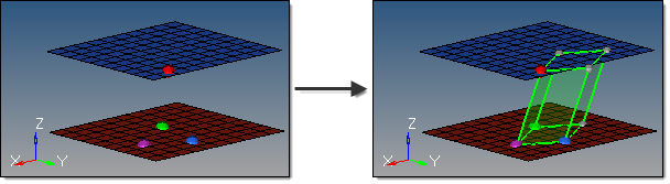
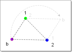
This subpanel creates three-dimensional block-shaped solid primitives.

solids_block_example

Four inputs are required to create a block using this method:

The base node defines the first corner on the bottom face.
Node 1 defines the corner of the bottom face that indicates the depth.
Node 2 defines the corner of the bottom face that indicates the width.

The bottom face of the block is then completed by rotating a copy of the triangle formed by these 3 nodes 180 degrees, and then matching the line between node 1 and node 2 for each triangle to create a parallelogram.

primitives_cube_1stface

Node 3 defines the corner of the top face that indicates the height and angle.

The vector from the base node to node 3 provides both the height and the angle for the block.  The parallelogram formed from the first set of nodes is translated along this vector to define the remaining faces.


hmtoggle_arrow1Cylinder Full solidCylinderFull-24

This subpanel creates fully-cylindrical, three-dimensional solid primitives.

solids_cylinderfull_example

Four inputs are required to create a cylinder using this method:

The bottom center node defines the center of the bottom cylinder face.
The vector between the bottom center node and the normal vector node is the cylinder axis, thereby defining the cylinder orientation.  This does not indicate the actual cylinder height.
The base radius defines the radius of the top and bottom cylinder faces.
The height defines the cylinder height.


hmtoggle_arrow1Cylinder Partial solidCylinderPartial-24

This subpanel creates three-dimensional, partial-cylinder solid primitives.

solids_cylinderpartial_example

Eight inputs are required to create a cylinder using this method:

The bottom center node defines the center of the bottom cylinder face.
The vector between the bottom center node and the normal vector node defines the cylinder axis, thereby indicating the cylinder orientation.  This does not indicate the actual cylinder height.
The vector between the bottom center node and the major vector node determines the zero-degree point of an arc defining the curved surface of the partial cylinder.  This arc extends in a direction based on the normal vector using the right-hand rule, with its start angle and end angle specified relative to this vector.
The base radius defines the radius of the top and bottom cylinder faces.
The height defines the cylinder height.
The start angle defines the starting arc angle, measured from the major vector node in a direction based on the normal vector using the right-hand rule.
The end angle defines the ending arc angle, measured from the major vector node in a direction based on the normal vector using the right-hand rule.  The difference between this and the start angle determines the arc of the partial cylinder, and therefore the arc of the cutout in the partial cylinder.  For example, if your start angle is 15 degrees, and your end angle is 285 degrees, the resulting cylinder has a base with a 270 degree arc and a 90 degree cut.
The axis ratio represents a percentage of the major vector.  This value must be greater than zero and less than or equal to 1.0.  Values other than 1.0 create oval-shaped cylinders instead of circular ones.

solids_cylinderpartial_ratio_example

With a ratio of 0.5 the cone is half as wide as its length.


hmtoggle_arrow1Cone Full solidConeFull-24

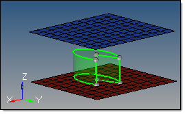
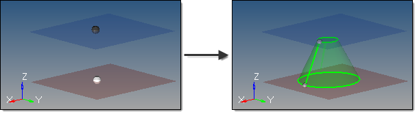
This subpanel creates three-dimensional, full-cone solid primitives.

solids_conefull_example

In this example, the cone is created with a top radius of 1.0; if the radius had been 0, it would taper to a point instead.

Five inputs are required to create a cone using this method:

The bottom center node defines the center of the bottom cone face.
The vector between the bottom center node and the normal vector node defines the cone axis, thereby indicating the cone orientation.  This does not indicate the actual cone height.
The top radius defines the radius of the top cone face.  If set to 0, a cone tip is created; if greater than zero, the cone has a flat top.
The base radius defines the radius of the bottom cone face.  This value must be greater than 0.
The cone height defines the distance between the cone's base and its top.


hmtoggle_arrow1Cone Partial solidConePartial-24

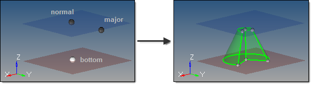
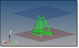
This subpanel creates three-dimensional, partial-cone solid primitives.

solids_conepartial_example

Five inputs are required to create a cone using this method:

The bottom center node defines the center of the bottom cone face.
The vector between the bottom center node and the normal vector node defines the cone axis, thereby indicating the cone orientation.  This does not indicate the actual cone height.
The vector between the bottom center node and the major vector node determines the zero-degree point of an arc defining the curved surface of the partial cone.  This arc extends in a direction based on the normal vector using the right-hand rule, with its start angle and end angle specified relative to this vector.
The top radius defines the radius of the top cone face.  If set to 0, a cone tip is created; if greater than zero, the cone has a flat top.
The base radius defines the radius of the bottom cone face.  Must be greater than 0.
The cone height defines the distance between the cone's base and its top.
The start angle defines the starting arc angle, measured from the major vector node in a direction based on the normal vector using the right-hand rule.
The end angle defines the ending arc angle, measured from the major vector node in a direction based on the normal vector using the right-hand rule.  The difference between this and the start angle determines the arc of the partial cone, and therefore the arc of the cutout in the partial cone.  For example, if your start angle is 15 degrees, and your end angle is 285 degrees, the resulting cone has a base with a 270 degree arc and a 90 degree cut.        
The axis ratio represents a percentage of the major vector.  This value must be greater than zero and less than or equal to 1.  Decimal values create oval-shaped cones instead of circular ones.

solids_conepartial_ratio_example


hmtoggle_arrow1Sphere Center and Radius solidSphereCenterAndRadius-24

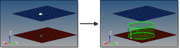
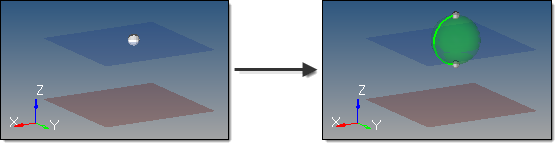
This subpanel creates three-dimensional sphere solid primitives by specifying the center and radius.

solids_sphere_centerandradius_example

Two inputs are required to create a sphere using this method:

The center node defines the center of the sphere.
The radius defines the sphere radius.  A value can be specified, or a node that defines the radius (measured from the center node) can be selected.


hmtoggle_arrow1Sphere Four Nodes solidSphereFourNodes-24

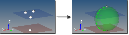
This subpanel creates three-dimensional sphere solid primitives by specifying four nodes.

solids_sphere4nodes_example

The selected nodes cannot all be coplanar. The smallest sphere that passes through all four nodes is created.  If more than four nodes are selected, only the four most recent are used.


hmtoggle_arrow1Torus Center and Radius solidTorusCenterAndRadius-24

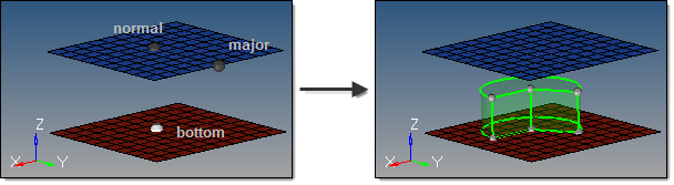
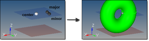
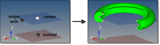
This subpanel creates three-dimensional torus solid primitives by specifying the center, normal direction, minor radius and major radius.

solids_torus_centerandradius_example

Four inputs are required to create a torus using this method:

The center node defines the center of the torus.
The vector between the center node and the normal vector node is the torus axis, thereby defining the torus orientation.
The major radius defines the outside radius of the torus, measured from the center node.
The minor radius defines the radius of the circular cross-section of the torus.


hmtoggle_arrow1Torus Three Nodes solidTorusThreeNodes-24

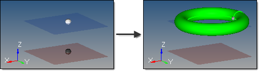
This subpanel creates three-dimensional torus solid primitives by specifying three nodes.

solids_torus3nodes_example

Three inputs are required to create a torus using this method:

The major center node defines the absolute center of the torus.
The minor center node defines the center of the circular cross-section of the torus.
The distance between the minor center node and the minor radius node defines the radius of the circular cross-section of the torus.

The three nodes must define a plane and cannot be collinear.  The circle defined on that plane by the minor center and radius is then spun around the major center to create the torus.


hmtoggle_arrow1Torus Partial solidTorusPartial-24

This subpanel creates three-dimensional partial torus solid primitives.

solids_toruspartial_example

This example shows a torus with partial start and end angles on both the major and minor radii.  The partial major
radius produces the broken/partial ring, while the partial minor radius produces the interior groove.  (Note that the
image of the torus is zoomed-in for better detail.)

Nine inputs are required to create a torus using this method:

The center node defines the absolute center of the torus.
The vector between the center node and the normal node is the torus axis.
The vector from the center node to the major axis node completes the definition of the torus plane.  Combined with the normal node, this provides the complete torus orientation.
The major radius defines the outside radius of the torus, measured from the center node.
The major start angle defines the starting arc angle for the major circumference (ring), measured from the torus plane in a direction based on the torus axis using the right-hand rule.
The major end angle defines the ending arc angle for the major circumference (ring), measured from the torus plane in a direction based on the torus axis using the right-hand rule.  The difference between this and the major start angle determines the major arc of the torus, and therefore the arc of the major cutout in the partial torus.  For example, if your major start angle is 15 degrees, and your major end angle is 285 degrees, the resulting torus is an open ring with a 270 degree arc and a 90 degree cut.
The minor radius defines the radius of the circular cross-section of the torus.
The minor start angle defines the starting arc angle for the minor circumference (cross-section), measured from the mid-plane of the cross-section in a direction based on the cross-section centerline using the right-hand rule.
The minor end angle defines the ending arc angle for the minor circumference (cross-section), measured from the mid-plane of the cross-section in a direction based on the cross-section centerline using the right-hand rule.  The difference between this and the minor start angle determines the minor arc of the torus, and therefore the arc of the minor cutout in the partial torus.  For example, if your minor start angle is 15 degrees, and your minor end angle is 285 degrees, the resulting torus has a cross-section with a 270 degree arc and a 90 degree cut.


hmtoggle_arrow1Bounding Surfaces solidBoundingSurfaces-24

This subpanel creates solids by converting closed surface shells which define the solid boundary.

solids_boundingsurfaces_example

Six inputs are required to create a solid using this method:

The surfaces that define the continuous, closed shell.  The surface selection must be completely closed; if the surface selection contains any free edges or gaps, a solid cannot be created. For example, a collection of surfaces representing an open cardboard box (like an empty cube, but with only five faces) will not work unless the sixth surface face is added.  Similarly, a selection of surfaces that has a tiny gap where two corners do not exactly meet also will not work.  When attempting to create solids in cases such as this, a red indicator will highlight problem areas.  Geometry cleanup tools, such as the Edge Edit or Quick Edit panels, can then be used to correct the issues.

No solid faces may be selected as input--only true 2D surfaces.

The auto select solid surfaces option allows for a single surface to be selected in the graphics area and the other surfaces that form a continuous shell are then automatically selected.  This is also useful to detect selections that may have errors, as a continuous shell will not be selected.

The create in method, which defines the resulting solid body component organization.

Specifying current component organizes the new solids and the selected surfaces to the current component.

Specifying surfs component adds the new solids to the same component that the selected surfaces already belong to.  If the input surfaces are in different components, the result is not predictable.


hmtoggle_arrow1Spin solidSpin-24

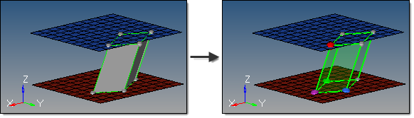
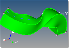
This subpanel creates solids by spinning surfaces around an axis.

solids_spin_example

This example spins the selected surface 120 degrees around the X axis at the base node, in the positive direction.

Seven inputs are required to create a solid using this method:

The surfaces to spin.

No solid faces may be selected as input.

The merge solids at shared edges option applies when one or more input surfaces are attached to each other.  This does not apply to single surface or unconnected surface selections.

If disabled, a solid is created for each input surface, with shared faces created at the shared edge locations.

If enabled, a single solid is created with merged faces created at the shared edge locations.

The create in method, which defines the resulting solids component organization.

Specifying current component organizes the new solids and the selected surfaces to the current component.

Specifying surfs component adds the new solids to the same component that the selected surfaces already belong to.  The result is unpredictable if surfaces from different components become a part of the same solid.

The plane/vector defining the rotation axis.  If a vector is defined or selected, this represents the axis of rotation.  If a plane is defined, the plane normal represents the axis of rotation.

The base node of the plane/vector represents the center of rotation.

The start angle defines the initial angle of the solid formed by the spin, measured about the axis of rotation using the right-hand rule. The selected surfaces will be rotated this many degrees before Altair HyperMesh extrudes the solid from them by an additional number of degrees determined by the difference between the start angle and end angle. Thus, each angle determines the position of one face along the arc of rotation, and therefore the difference between start and end angles determines the thickness of the solid through the arc.
The end angle defines the final angle through with the surfaces are spun, thus determining the solid's thickness along the arc of rotation.  The angle is measured about the axis of rotation using the right-hand rule.  The total angle is given by (end angle - start angle).
The direction of the spin.

Spin + is defined using the right-hand rule around the axis of rotation and uses the start angle and end angle values as specified.

Spin - is defined in the opposite direction and uses the negative of the specified start angle and end angle values.


hmtoggle_arrow1Drag Along Vector solidDragAlongVector-24

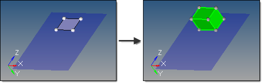
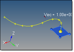
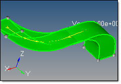
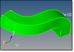
This subpanel creates solids by dragging surfaces along a vector.

solids_dragalongvector_example

Eight inputs are required to create a solid using this method:

The surfaces to drag.
-Solid faces can be selected as input.
The plane/vector defining the drag direction.  If a vector is defined or selected, this represents the positive drag direction.  If a plane is defined, the plane normal represents the positive drag direction.
The Keep connectivity option maintains the connectivity of the input surfaces to any attached surfaces. If the input surface is part of a solid, this must be enabled.
The merge solids at shared edges option applies when one or more input surfaces are attached to each other.  This does not apply to single surface or unconnected surface selections.
-If disabled, a solid is created for each input surface, with shared faces created at the shared edge locations.
-If enabled, a single solid is created with merged faces created at the shared edge locations.
The create in method, which defines the resulting solids' component organization.
-Specifying current component organizes the new solids and the selected surfaces to the current component.
-Specifying surfs component adds the new solids to the same component that the selected surfaces already belong to.  The result is unpredictable if surfaces from different components become a part of the same solid.
The distance defines the length to drag the surface along the vector.
The direction of the drag.
-Drag + is defined using specified vector direction.
-Drag - is defined in the opposite direction.
The inflate button creates a new solid from surfaces, by extruding the surface in both directions by half of the specified thickness.


hmtoggle_arrow1Drag Along Line solidDragAlongLine-24

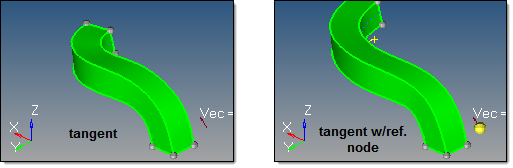
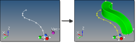
This subpanel creates solids by dragging surfaces along a line.

solids_dragalongline_example

Eight inputs are required to create a surface using this method:

The lines or node list to drag.
-If a node list is specified, a line will first be fit through the specified nodes.
-The line list that defines the lines that the drag will follow.  This can also be a series of connected lines.
The merge solids at shared edges option applies when one or more input surfaces are attached to each other.  This does not apply to single surface or unconnected surface selections.
-If disabled, a solid is created for each input surface, with shared faces created at the shared edge locations.
-If enabled, a single solid is created with merged faces created at the shared edge locations. continuous lines.
The create in method, which defines the resulting solids' component organization.
-Specifying current component organizes the new solids and the selected surfaces to the current component.
-Specifying surfs component adds the new solids to the same component that the selected surfaces already belong to.  The result is unpredictable if surfaces from different components become a part of the same solid.
The frame mode defines how the surfaces are translated and rotated during the drag.  Each of the following examples uses this starting model:

solids_dragalongline_framestart

fixed frame: the surfaces are only translated during the drag, not rotated.

solids_dragalongline_fixedframe

line tangent: in addition to the translation of the fixed frame option, the surfaces are also rotated in the same way that the tangent of the line list rotates.

solids_dragalongline_tangent

Frenet frame: in addition to the translation and rotation of the line tangent option, the surfaces also rotate around the line list tangent axis in the same way as the curvature vector rotates.

solids_dragalongline_frenetframe

The Frenet frame option does not work well when the curvature of the line is not smooth or there are large jumps.

The reference node and transformation plane options require the following definitions:

S:  start of drag line, which is the closest end of the line to the surface vertices. Drag + follows this direction. Drag - follows the opposite direction.

T:  tangent of drag line at S.

R:  reference node.

B:  base node of the transformation plane.

N:  normal vector of the transformation plane.

The reference node (R) is used to translate the drag line prior to the drag.  By default, R=S.  If a different S is specified, the line list is translated by the vector defined from S to R.

solids_dragalongline_refnode

The transformation plane is used to translate and rotate the input surfaces prior to the drag.  By default, no transformation occurs (B=R and N=T).  If specified, the surfaces are translated by the vector defined from R to B, and are rotated from N to T.

solids_dragalongline_transformationplane

The direction of the drag.

Drag + is defined at the start of drag line, which is the closest end of the line to the surface vertices.

Drag - is defined in the opposite direction.


hmtoggle_arrow1Drag Along Normal solidDragAlongNormal-24

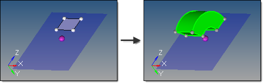
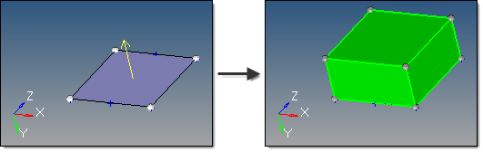
This subpanel creates solids by dragging surfaces along their normal.

solids_dragalongnormal_example

The yellow arrow displays once the surface is selected, and indicates the surface normal.

Five inputs are required to create a solid using this method:

The surfaces to drag.
-Solid faces can be selected as input.
The Keep connectivity option maintains the connectivity of the input surfaces to any attached surfaces. If the input surface is part of a solid, this must be enabled.
The merge solids at shared edges option applies when one or more input surfaces are attached to each other.  This does not apply to single surface or unconnected surface selections.
-If disabled, a solid is created for each input surface, with shared faces created at the shared edge locations.
-If enabled, a single solid is created with merged faces created at the shared edge locations.
The create in method, which defines the resulting solids component organization.
-Specifying the current component organizes the new solids and the selected surfaces to the current component.
-Specifying the surfs component adds the new solids to the same component that the selected surfaces already belong to.  The result is unpredictable if surfaces from different components become a part of the same solid.
The distance defines the length to drag the surface along its normal.
The direction of the drag.
-Drag + is defined using the surface normal direction.
-Drag - is defined in the opposite direction.


hmtoggle_arrow1Ruled Linear solidRuledLinear-24

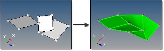
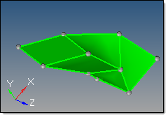
This subpanel creates solids by interpolating linearly between surfaces.

solids_ruledlinear_example

Five inputs are required to create a solid using this method:

The surface list to use.  A linear interpolation is used between each pair of surfaces in the selection to create the solid.  Multiple surfaces at the same level can be selected, as long as the selection order between different levels is not mixed.
-Solid faces may be selected as input.
The create ring solid option specifies whether the first and last surfaces in the list should be considered as a pair in order to form a closed loop solid.
The split solid at shared surfaces option specifies how the resulting solid is split.  If enabled, the solid is split at each of the input surfaces to create multiple solids with shared surfaces.  If disabled, a single solid is created without shared faces.
The create in method, which defines the resulting solids component organization.
-Specifying the current component organizes the new solids and the selected surfaces to the current component.
-Specifying the surfs component adds the new solids to the same component that the selected surfaces already belong to.  The result is unpredictable if surfaces from different components become a part of the same solid.
The link type option determines whether user-defined links are used to provide better interpolation and shape control.
-When set to default, any user-defined links or guiding lines/surfaces are ignored.

solids_ruledlinear_linktype_default

-When set to select links, node/point links can be defined.  Node/point links are input as pairs since a link between input surfaces is specified by its two end points/nodes. Furthermore, a pair may not skip any surface in between.  For instance, if surfaces 1, 2, 3 and 4 are defined in that order as the input surface list, a link can be defined from surface 2 to 3 but not from surface 2 to 4.  If such a link is detected, it is ignored.  One point/node may be linked to multiple points/nodes, which results in the creation of triangular surfaces.  Node/point links show graphically as a white line between the pairs, with an L at the line center.  To disable a pre-defined link, right-click the L graphic.  To re-enable a disabled link, left-click the L graphic.

solids_ruledlinear_linktype_select


hmtoggle_arrow1Ruled Smooth solidRuledSmooth-24

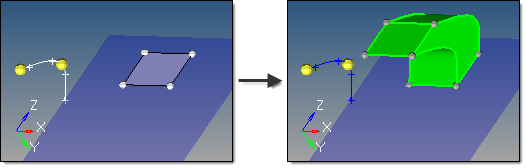
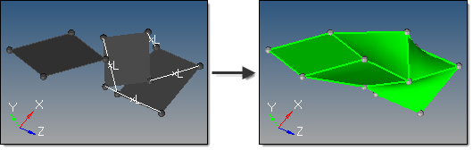
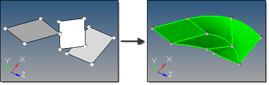
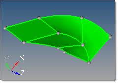
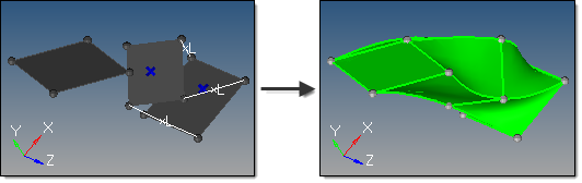
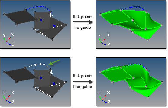
This subpanel creates solids by interpolating smoothly between surfaces.

solids_ruledsmooth_example

Five inputs are required to create a solid using this method:

The surface list to use.  A smooth interpolation is used between each pair of surfaces in the selection to create the solid.  Multiple surfaces at the same level can be selected, as long as the selection order between different levels is not mixed.
-Solid faces may be selected as input.
The create ring solid option specifies whether the first and last surfaces in the list should be considered as a pair in order to form a closed loop solid.
The split solid at shared surfaces option specifies how the resulting solid is split.  If enabled, the solid is split at each of the input surfaces to create multiple solids with shared surfaces.  If disabled, a single solid is created without shared faces.
The create in method, which defines the resulting solids component organization.
-Specifying the current component organizes the new solids and the selected surfaces to the current component.
-Specifying the surfs component adds the new solids to the same component that the selected surfaces already belong to.  The result is unpredictable if surfaces from different components become a part of the same solid.
The link type option determines whether user-defined links are used to provide better interpolation and shape control.
-When set to default, any user-defined links or guiding lines/surfaces are ignored.

solids_ruledsmooth_link_default

-When set to define links, node/point links can be defined.  Node/point links are input as pairs since a link between input surfaces is specified by its two end points/nodes. Furthermore, a pair may not skip any surface in between.  For instance, if surfaces 1, 2, 3 and 4 are defined in that order as the input surface list, a link can be defined from surface 2 to 3 but not from surface 2 to 4.  If such a link is detected, it is ignored.  One point/node may be linked to multiple points/nodes, which results in the creation of triangular surfaces.  Node/point links show graphically as a white line between the pairs, with an L at the line center.  To disable a pre-defined link, right-click the L graphic.  To re-enable a disabled link, left-click the L graphic.

solids_ruledsmooth_link_points

-In addition, guiding lines and guiding surfaces can be defined when define links is selected.
-Guiding lines are used to indicate part of the boundary of the final interpolated solid. If more than one guiding line is selected, the edges of the solid between these lines are obtained by smoothly interpolating the lines.  If a guiding line extends beyond the input surfaces, that part of the line is ignored.

solids_ruledsmooth_link_guideline

-In order for guiding lines to be valid, they must:
a)Connect the input surfaces at their boundaries.
b)Connect to all intermediate input surfaces.
-In order for guiding surfaces to be valid, they must:
a)Link the step surfaces as a single-piece surface.  In other words, if edge-A of a step surface is linked to edge-B of a step surface the linking surface must be a single surface.
b)Be stitched to the edges of step surfaces.
c)Link all the level surfaces of the solid.  For example, if there are 3 step surfaces and one wants to use guiding surfaces, it is not enough to link only bottom and middle surfaces by a guiding surface. One needs to link the middle and the top surface also.
d)If two or more guiding surfaces are located next to each other, they must be stitched together properly.
-If any conditions are not met, those guiding lines/surfaces will be ignored.

In the case of a surface with a scratch, if one of the internal points of the scratch is not linked to another surface at its boundary, this scratch is treated as if it is not part of the boundary, that is, as if it does not exist.  If the scratch is linked upward but not downward, then is it considered a part of the boundary while constructing surfaces between its level and the level above, but it is ignored while constructing boundary with the surface below.

All the surfaces at each level must have the same number of internal loops, if any.  Currently, only one internal loop at each level is supported.  Cases with more than one internal loop will generate solids, but the matching between loops may not be desirable.