Applying a Characterised Surface to a Face
Apply a characterised surface to a face bordering free space or dielectric regions.
When a characterised surface definition is applied to an RL-GO face, a vector is required to ensure the correct surface orientation. The U vector that is provided should point in the direction of the U vector (or X vector in global coordinates) when the surface was characterised (either through simulation using periodic boundary conditions, an infinite ground plane or measurements). The projection of the U vector onto the face correspond to the U vector (or principal direction) of the characterised surface.
Curved surfaces such as radomes have to be split into smaller faces so that a valid U vector can be defined for each surface. As an illustration, consider a sphere. There is no single vector that has a valid projection onto the surface of a sphere, since at two points, the vector points in the direction of the face normal.
-
On the Face properties dialog, click the
Properties tab.
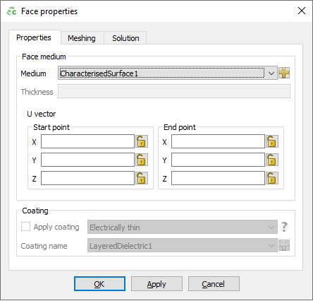
Figure 1. The Face properties dialog (Properties tab).
The U-Vector is defined as the reference direction projected onto the face.
-
Under U vector, specify the start
point and end point for the U-Vector. The vector is not
required to be exactly in the plane of the face, since it is projected onto the
face, but it should be approximately parallel to the face.
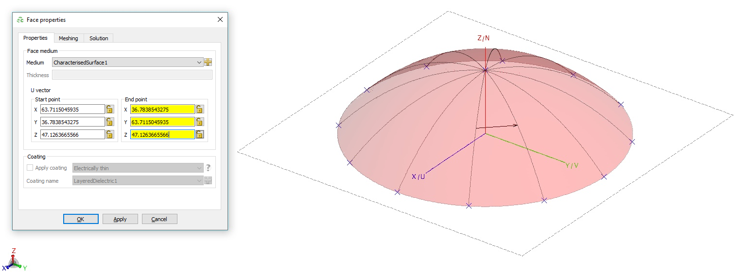
Figure 2. The display in CADFEKO when setting the U-Vector. Opacity settings were modified in order to see the U-Vector preview.
Ensure that the RL-GO solution method is selected on the Solution tab. The characterised surface feature is only supported in conjunction with the RL-GO solution method.
-
Click the OK to apply the characterised surface
and to close the dialog.
The U-Vector can be displayed in POSTFEKO to verify that all faces have the correct settings and U-Vector orientations applied.
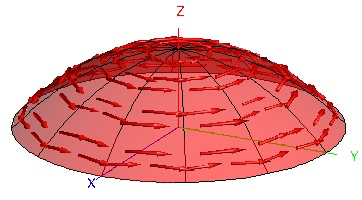
Figure 3. Characterised surface orientation displayed in POSTFEKO where each face has a different U-Vector applied.