Setting-Up Common Parameters
The table below resumes the common parameters taken into account in the following
examples:
| Data | Definition | Values |
|---|---|---|
| Frequency | Simulation frequency | 5 GHz |
| Material 1 | Dielectric constant of Material 1 | 4 - 0.08·j |
| Material 2 | Dielectric constant of Material 2 | 1.1 - 0.0055·j |
| Thickness | Constant thickness of material 1 | 0.25 mm |
| t | Parametric thickness of material 2 | 3 , 3.5 , 4, 4.5, 5 mm |
| Units | Units for working in newFASANT | Millimeters |
Now, we set-up the parameters of this table within a project that will be copied and renamed for all the configurations shown.
- Create a new MOM project. To do that, click on New Project button
and select the MOM module.
Figure 1. Choose the MOM module - Set the units. Click on the current units and select Millimeters
to make easier working with the thickness.
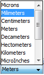
Figure 2. Set units to Milimeters unit - Set the frequency. Click on Simulation – Parameters menu and then
the Simulation panel is open on right side of screen. Set the frequency to 5 GHz
and click on Save button before closing the panel.
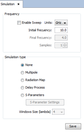
Figure 3. Set the frequency to 5 GHz - Define the materials. Click on Materials – Add menu and then the
Add Material panel is open on right side of screen. Set the
Name and Color of the materials to be defined, keep the default
Material Definition option, that is Material defined by geometry, and
then click on Set Parameters button to specify the dielectric values of each
material (click on OK button within the Geometry Material window to
confirm the dielectric constant assigned). Remember clicking on Save
button after defining every material.
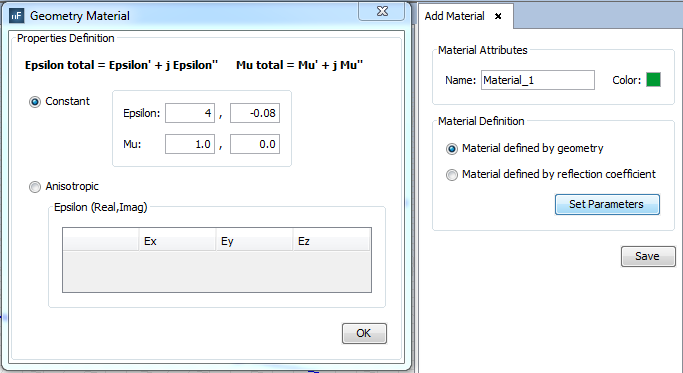
Figure 4. Material 1 definition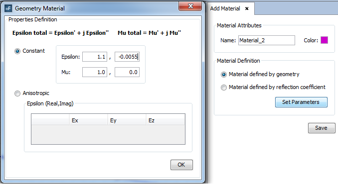
Figure 5. Material 2 definition - Define the parameters. Click on Geometry – Parameters – Define
Parameters, and then the Define Parameters panel is open on right side
of screen. Unless it is not necessary to add the thickness of the Material 1 as
a parameter because it has a fixed value, we will define its parameter to create
the geometry also as a full parametric model. To assign a fixed value to a
parameter, the value must be inserted between “{ }” characters. The interesting
parameter is the thickness of the Material 2, which we have named t, and it must
be ranging between 3 and 5 millimeters. To assign a range of values to a
parameter, the initial and end values are inserted between “[ ]” characters and
separated by spaces, and then the number of samples must be specified. Remember
click on Save button before closing this panel.
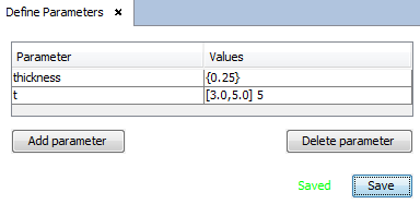
Figure 6. Parameters definition - Save the project. Click on File – Save As menu and specify where you want to save this project, which will be used as base project for the next example. We have named it as baseProject.nfp. Then, for every example we will copy and rename this base project and only will have to set-up the antenna and the radome.
- Solver parameters. Click on Solver – Parameters menu to open the
Solver panel on right side. The only parameter to be modified in this document
may be the Preconditioner one that may be enabled or disabled for
speeding-up the solver convergence. Click on Advanced Options button to
open the Solver Advanced Options window, then select the Preconditioner
tab and enable or disable the option Enable Precontioner as desired.
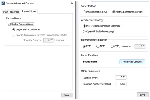
Figure 7. Preconditioner Solver options